A Complete Guide ATEX Flameproof Instrumentation Panel
- shreeelectric
The acronym ATEX stands for “ATmosphere EXplosible.” ATEX is also the shortened name for the European Directive 2014/34/EC on the marketing of explosion-proof electrical and mechanical equipment, components, and protective systems.
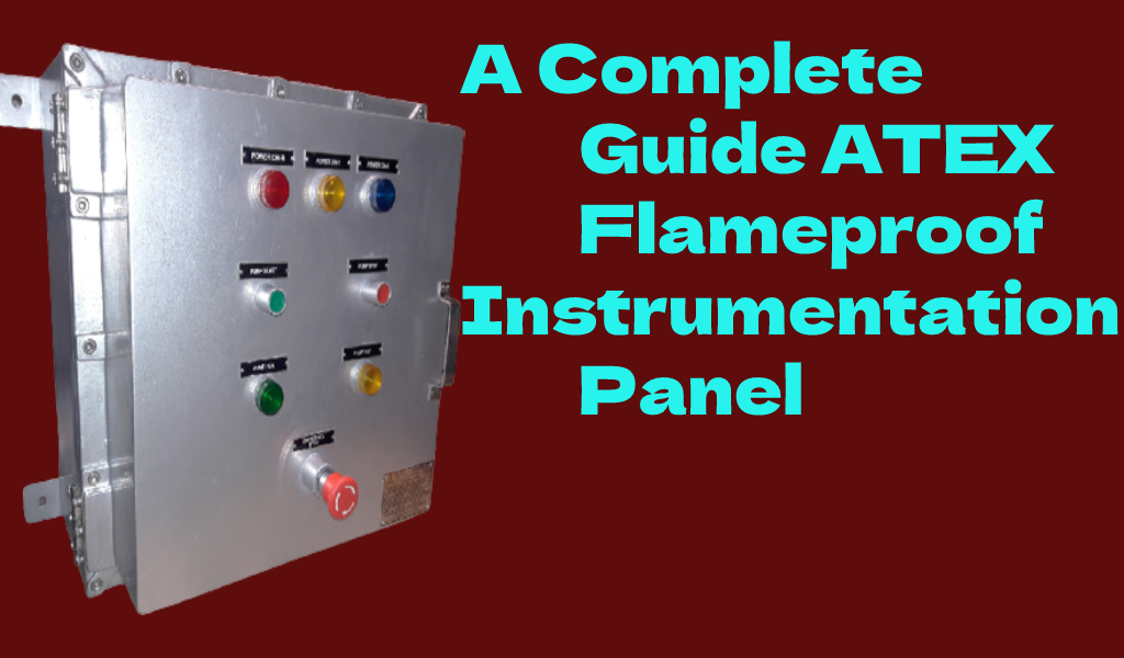
Heater Control Flameproof Enclosure, ATEX Flameproof Weatherproof Instrument Control Panel, Flameproof Weatherproof Instrument Panel For Process Control, and ATEX Instrument Enclosure are some of the products offered by Shree Electrical. The design and fabrication of an ATEX FLP Instrument control panel is based on the client’s specifications. The Atex FLP instrument Panel is used in places where system control is critical.
ATEX zones are categorised based on two factors: the sorts of combustibles that may be encountered (dust or gas) and the frequency or duration of an explosive atmosphere. Before consulting the technical advice itself, carefully read the Instructions for Use.
Difference Between Intrinsically Safe And Flameproof Equipment
Suppose a failure occurs in a piece of electrical or electronic equipment positioned in a location with combustible gases. In that case, the malfunction might generate enough heat or sparks to ignite the gas and create a calamity. Two strategies are commonly used to prevent such occurrences.
1. Flameproof / Explosion-Proof Equipment
The equipment is enclosed in a hefty protective enclosure, which is typically composed of die-cast steel and, on occasion, plastic. The resultant explosion is contained within the enclosure if heat or sparks from defective equipment ignite combustible gas. Metal conduits must be used for field wiring in North America. In Europe and abroad, approved flameproof cable glands are used to connect the appropriately rated cable directly to the equipment.
- Advantage: The system is simple to construct and is appropriate for high-power equipment.
- Disadvantage: It includes increased equipment weight and cost, as well as the inability to open the enclosure while it is powered.
2. Intrinsically Safe
This method restricts the energy accessible to intrinsically safe (I.S.) equipment to less than 2 watts through a galvanic or Zener barrier, ensuring that the equipment cannot create enough heat or sparks to ignite hazardous gases. BASEEFA, SIRA, or a similar organisation must certify the I.S. equipment and the Zener barrier as “Intrinsically Safe.”
- Advantage: Significantly less expensive than equivalent flameproof/explosion-proof equipment, and no special cabling is necessary. Live maintenance is allowed. There is no reason to shut down the factory.
- Disadvantage: The disadvantage is that it is only suited for low-power devices such as sounders, beacons, and smoke detectors (which must be certified Intrinsically Safe)
Explosion proof / Flame proof (ATEX & ICEX equipment certified Exd & North American Class 1 Division 2 equipment)
- The phrases “explosion proof” and “flameproof” are sometimes used interchangeably. Although there are some slight distinctions, engineers and the market in general use both names to denote the same thing: a piece of electrical equipment built for usage in a hazardous environment via a heavy duty enclosure.
- Any system that uses ATEX or ICEX Exd certified equipment, such as E2S Ltd. BEX series sounders or GNEX series xenon beacons, must utilise appropriately rated and mechanically protected cable. Exd approved cable glands and junction boxes must be used to terminate the cable. The glands and junction boxes must be Exd certified to the same level as the field equipment by BASEEFA, SIRA, or another recognised organisation.
Connection Cabling Requirements
Although the kind of cable used in I.S. circuits are not restricted, all cables have inductance, capacitance, and hence energy storage capacities; consequently, they can impair system safety. A cable’s capacitance and inductance values should be easily available from the cable manufacturer.
Furthermore, the capacitance and inductance values of field-mounted devices such as I.S. sounders and smoke detectors must be considered; these values should be easily accessible from the manufacturer. As a result, the system design limits the quantity of each of these characteristics. Much has been published on the matter, but only rarely is a substantial restriction imposed on the available cable. The cabling must meet the following specifications.
- Be resistant to mechanical harm
- Be resistant to chemical assault, such as acids
- Be securely fastened
- Have a minimum conductor size of 0.017mm2
- Pass a 500V insulation test
- Have a circuit voltage of no more than 60V
The Following Cables Can Be Used:
- Instrument cable with a screen
- Multi-core signal cable (e.g., telephone cable) subject to screening and earthing requirements
- Multi-core micro electric cables
- Standard cables with standard insulating bundles, such as P.V.C. with a minimum insulation thickness of 0.3mm.
Junction boxes used in inherently safe circuits are not subject to any specific criteria. They must, however, be identified as being part of an intrinsically safe system.
Installation Of Cables Used In Intrinsically Safe Circuits: IEC 60079-14 requires the installation of I.S. devices and accompanying equipment. Cable trays, ducts, and conduits carrying inherently safe circuits should be kept segregated from other cable trays, ducts, and conduits. It should be noted that in the United Kingdom, I.E.T. Wiring standards forbid electrical services, such as power and lighting circuit cabling, from being carried in the same conduit or duct as I.S. circuits.
Installation Of Cables Used In Intrinsically Safe Circuits
Separating cable trays, ducts, and conduits carrying inherently safe circuits from trays and ducts carrying any other cables, such as telephone and computer cables, is generally regarded as good practice. Electrical services, such as electricity and lighting, are not permitted to be carried in the same conduit under I.E.E. wiring rules.